INSTALLING
THE CHART PAPER
The recorder accepts
three different types of chart paper. Charts are available for 1, 7 and
32 day recording times. Although chart paper replacing is very simple,
you must take care to set the appropriate front panel switches to match
the paper being used. Set the chart type and Cal/Normal switches (refer
to Figure 2-7) to the following positions for these three (3) modes of
operation. Figure
2-1 shows the removal of the decorative foot cover.
|
Chart
Type Switch (Days)
|
CAL/NORMAL
|
Paper
Type
|
|
1
|
C
|
1-day,
Celsius and pH paper |
|
7
|
C
|
7-day,
Celsius and pH paper |
|
32
|
C
|
32-day,
Celsius and pH |
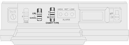
Figure 2-7.
Chart Switches
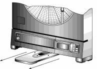 Figure
2-8. Stabilizing Arm Fully Extended
|
To
change the chart paper:
1a. Table Mounted Recorder
To balance the recorder, fully extend the stabilizing arm at the bottom
of the recorder. Refer to Figure 2-8. Continue to Step 2.
1b. Wall Mounted
Recorder:
You can also leave the recorder on the wall if it is easily accessible.
2. Open the door and hold it open with left hand.
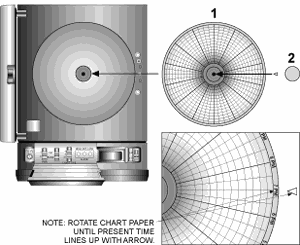 Figure
2-9
Changing Chart Paper and Setting the Time
|
3. Remove the
magnetic chart paper knob (Figure 2-9, item #2) and used chart paper.
4. Place the new chart paper (Figure 2-9, item #1) on the spindle
and rotate it until the current time on the chart paper is aligned with
the time arrow on the chart base of the recorder. See Figure 2-9 detail.
5. When the chart paper is correctly oriented, replace the magnetic
knob (Figure 2-9, item #2), being careful not to alter the position of
the chart paper.
6. Make sure that the ôChart Typeö switch, located behind the control
panel door, is in the correct position relative to the chart paper used.
NOTE: If the switch is in the wrong position, the chart paper will
not rotate at the correct speed and the indicated chart time will not
correspond to real time.
Installing
and Removing Pens
The recorder uses two
different colored pens to record information. The green (upper) pen records
pH. The red (lower) pen records temperature. Pen life varies with use
and climate. Under normal operating conditions, pens last at least one
month. We recommend that you install a fresh set of pens after every month
of use.
1. Make sure
the power switch on the front panel is in ôOö position. The front panel
is located under the control panel door. The recorder door should be closed.
NOTE:
The control panel door opens easily by gently gripping the recessed area
at the right side and slowly pulling down.
2. Examine the location of the pen arms through the window in the
recorder door.
a.
If the pen arms are offset as shown in Figure 2-10,continue to
Step 3:

Figure 2-10. Offset Alignment of
Pens
(for ease of pen installation)
|
b.
If
the pen arms are vertically aligned as shown in Figure 2-11, do
the following and then proceed to Step 3.

Figure
2-11. Vertical Alignment of Pens
(pens canÆt be inserted)
|
(The pen arms must
be offset sufficiently to allow for clearance before insertion or removal
is attempted. The pens must be moved electrically.)
- Make sure the
recorder door is closed and a piece of chart paper is installed on
the spindle on the chart base.
- Turn the unit
back on by moving the power switch to ô|ö and wait for the pens to
be far enough apart to remove a used pen one at a time or to insert
a new pen one at a time.
 CAUTION:
DO NOT ATTEMPT TO OFFSET THE PENS MANUALLY (BY HAND). THE DRIVE MECHANISM
COULD BE DAMAGED. DO NOT ATTEMPT TO CHANGE THE PENS WHILE THEY ARE IN
MOTION. CAUTION:
DO NOT ATTEMPT TO OFFSET THE PENS MANUALLY (BY HAND). THE DRIVE MECHANISM
COULD BE DAMAGED. DO NOT ATTEMPT TO CHANGE THE PENS WHILE THEY ARE IN
MOTION.
- Turn off the
unit (PWR switch position in ôOö position) to stop the pen movement.
3. Open the recorder door by applying downward pressure on the
latch button (refer to Figure 1-1, item #16).
4. Remove the pens from the package and the cap from each pen.
We recommend that you put the pen caps on special posts located on the
chart base of the recorder near the light bulbs.Figure 2-12 shows the
location of the posts.
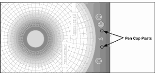
Figure 2-12. Post Location for
Pen Caps
|
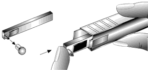
Figure 2-13. Pen Installation
|
5. Insert the
red pen fully into the lower (temperature) holder and the green pen fully
into the upper (pH recorder) holder. If you installed the pens correctly,
you will hear a click as they position themselves in the holders. Figure
2-13 shows how to insert the pens.
6. Close the recorder door.
Removing
the Pens
1. Check to see that the pens are offset as shown in Figure 2-10.
Otherwise, you can damage the arm and drive mechanism if you try to remove
them.
 CAUTION: DO NOT ATTEMPT TO OFFSET THE PENS MANUALLY (BY HAND). THE
DRIVE MECHANISM COULD BE DAMAGED. DO NOT ATTEMPT TO CHANGE THE PENS WHILE
THEY ARE IN MOTION.
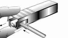
Figure 2-14. Pen Removal
|
2. Perform Step
2b in Section 2.5.1 to offset the pens.
3. With a screwdriver
in one hand, push on the rectangular area of the pen shown in Figure 2-14.
Using the other hand, release the pen from the spring clip attached to
the pen holder.
4. At
the same time, slide the pen out from the pen holder.
5. Install new pens following Section 2.5.1, Steps 3
Installing the pH/Temperature
Sensor
The pH/temperature
sensor can either be directly attached to the recorder using its own attached
short cable or be extended by using the remote sensor cable.
Using
the Short Cable
1. Place the
handle part of the sensor in to the sensor clip on the side of the recor
der.
2. Install the connector into the socket at the side of the recorder.
Make sure the sensor cable is untwisted.
Using
the Remote Sensor Cable
1. Connect
the end of the cable with the arrow to the short cable on the
sensor. Line up the two arrows as shown in Figure 2-16 before
mating the two cables.
2. Connect the other end of the remote sensor cable (without
the arrow) to the socket at the side of the recorder.
Figure
2-16.(On right)
Using the Remote Sensor Cable
|
|
|